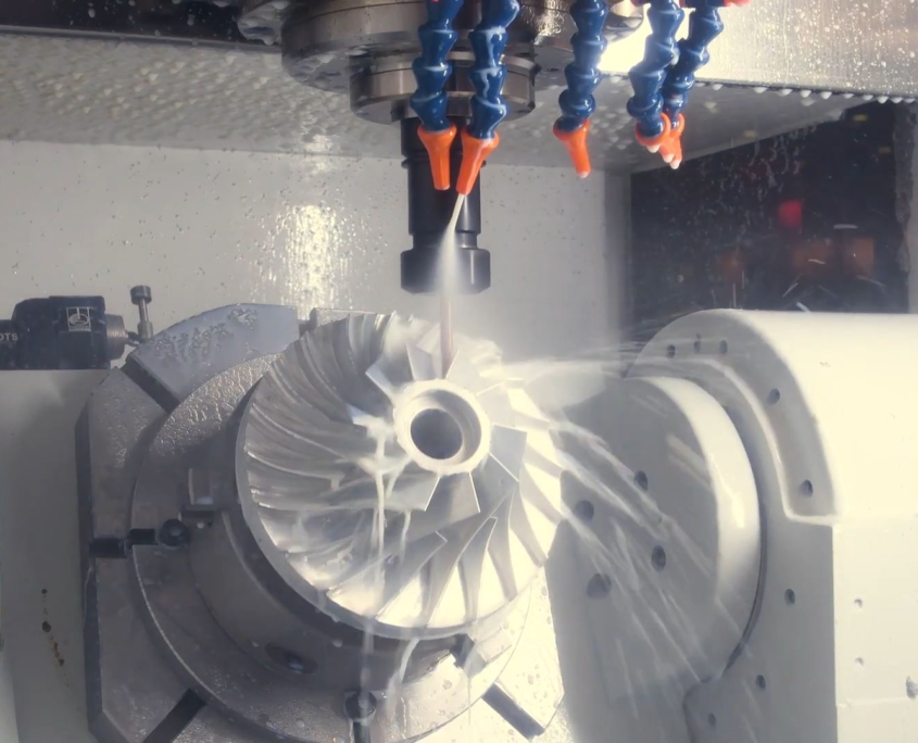
A flow-through motor that uses the energy of a flowing medium to produce mechanical energy is a very complex mechanical device. Currently, these types of constructions are used in the energy and transport industries. The design of turbojet engines and power turbines is similar, and later the aspects of the implementation of key elements will be discussed. The main structural element in addition to the outer casing is the shaft on which the drum or wreath forming the palisade is mounted. These elements form a set called rotor.
Countless blades included in the palisade are responsible for contact with the flowing medium. As a result, a torque is generated on the rotor shaft that sets the entire turbine in motion. There are also turbine constructions in which the rotor is a monolithic element, containing solid blades connected to the hub without the possibility of dismantling individual parts. The rotor in this solution is made of one block of material. Such a solution occurs e.g. in the automotive industry in turbo-compressors of supercharged internal combustion engines.
Currently, two technologies of making fixed (monolithic) rotors are distinguished. The first is to make the rotor as a cast in a previously prepared form. In the case of series production of turbines, it is a cost-effective method, however, impellers made in this way have disadvantages. The first is the big difference in the homogeneity of the material structure of the cast rotor. This results in a reduction in strength. At high rotational speeds, reduced strength may cause the rotor to burst. The second drawback eliminating the casting method in heavier structures is uneven rotor balancing. This generates an additional verification process, and also involves the need to improve balance and introduce geometric changes in already made elements. In structures that require high strength and long reliability, rotors made of a material block are used by milling turbines, rotors using multi-axis numerically controlled machines.
The use of advanced machining centers, whose construction kinematics allow the tool to be positioned in relation to the workpiece in any position, requires preparation of machining technologies in CAM class support systems. CAMWORKS is a system offering very advanced functions.High technological requirements justify the use of advanced machining centers in the process of producing turbine elements, and knowledge and practice on machining rotors is the key to their proper implementation.

